Download Manager
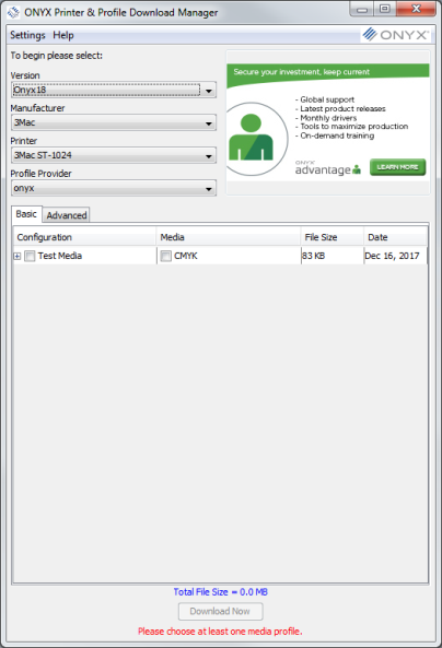
Using the Printer and Profile Download Manager application, you can view the list of the latest media profiles available for ONYX printer drivers.You can select a custom set of profiles to download and then easily install them into your ONYX product. The Download Manager application also offers the ability to get printer driver updates. The Printer and Profile Download Manageris installed with the ONYX product.
Windows 7, Windows 8, and Windows 10 users:
 Downloading the Printer and Profile Download Manager:
Vestel 17ips12 Schematic ~repack~ Link
g., no power vs. no backlight) or need a for common replacements? vestel 17ips12-r3 psu sch - service manual - Elektrotanya
is an integrated board that combines the main power supply and the LED backlight driver. Vestel 17ips12 Schematic
: Two boards may look identical but have different output currents for LEDs Selection Rule : Always match the production number vestel 17ips12 schematic
If you are looking for specific repair details, the 17IPS12 is characterized by: Primary Voltages : Typically produces +12V DC and +24V DC outputs. Key Components
The 12V and 24V rails . If they are absent, check the PS_ON pin at the mainboard connector. If PS_ON is high (>2V) but no 12V/24V, the fault is in the primary switching section. Check: Secondary diodes on 12V/24V lines. 3. Sound But No Picture (Backlight Issue) This is the most frequent 17IPS12 failure. Check: The 24V line feeding the LED driver . Check: The Boost Diodes and MOSFET in the driver circuit. Vestel 17ips12 Schematic : Two boards may look
Main fuse (F100) and the primary switching MOSFET (Q100).
: The transformer provides multiple secondary windings to produce: : Used for general system logic and audio. : Primarily for the backlight inverter or driver stage. Standby Voltage (+5V) If PS_ON is high (>2V) but no 12V/24V,
The most accurate and reliable schematic for the Vestel 17IPS12 is primarily available from two key online sources:
A TV showing absolutely no sign of life—no standby light, no sound—often has a primary-side fault. The Fix : Check the main fuse for continuity. If it is blown, do not simply replace it. A blown fuse is a symptom of a short downstream. Using a multimeter in diode mode, check for shorts in the primary circuit. Pay close attention to:
The 17IPS12 schematic is divided into several critical stages that manage power conversion and regulation: Primary Input & Rectification
is a complex board that combines several key power stages into one unit: